Scroll Top

Installation

Installation

Installation Instructions

First Things First
  1. Unpack the Grease Boss and read all the documentation.
  2. Ensure the Grease Boss has a current electrical test tag.
  3. Ensure the power supply can be easily located and the Grease Boss can be easily disconnected or isolated from the power supply.
  4. Do not connect power until the Grease Boss is fully installed and all plumbing connections have been checked
Connections

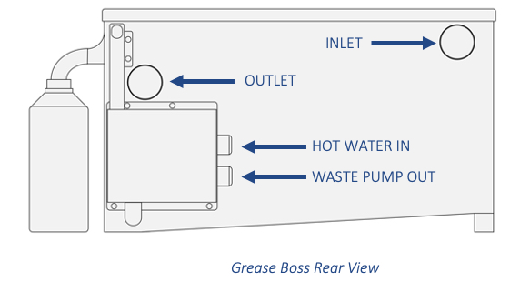
The Grease Boss has four plumbed connections:

  1. A waste pump-out connection with a supplied flexible hose.
  2. A hot water inlet of ¾ pipe fitting (standard laundry fitting).
  3. An outlet socket of 50mm diameter stainless tube located at the rear of the Grease Boss. The outlet MUST be plumbed with 50mm.
  4. An inlet socket of 50mm diameter stainless tube located at the rear of the Grease Boss.

The Grease Boss is supplied with two 90-degree flexible couplings for connection to the inlet and outlet sockets.

Inlet and Outlet Connections

The inlet and outlet sockets are 50mm stainless tube and are located at rear of Grease Boss. The sockets are easily connected with the supplied 90-degree flexible coupling or other satisfactory connection. A running trap or P-trap should be installed on the outlet to avoid any odour from the utility mains.

Ensure a minimum 2 degree fall to allow the Grease Boss to drain freely.

Hot Water Connection

The Hot Water connection is located at the rear of the Grease Boss. The Hot Water connection is labelled “HOT WATER” and supplies the internal cleaning jets and is essential to ensure the liquidity of the FOG. The connection is a ¾ pipe fitting suitable for a standard laundry hose or similar. Ensure that the Hot Water connection is connected to a constant supply of hot water in excess of 45oC at mains pressure.

THE GREASE BOSS CANNOT OPERATE EFFECTIVELY WITH LOW PRESSURE HOT WATER

The Grease Boss maintains an air gap between the hot water jets and the maximum operational water level. It is, however, theoretically possible for the internal water level to reach the jets if the outlet is restricted. MACTRAP recommends a dual check valve be installed at the hot water source in accordance with Local Authority regulations.

A DUAL CHECK VALVE SHOULD BE INSTALLED AT THE HOT WATER SOURCE

Pump Out Connection
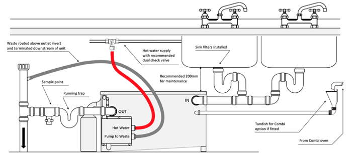
The Grease Boss has an automatic pump out facility. The pump out connection is located immediately below the hot water connection and is labelled “WASTE”. The Grease Boss is supplied with a flexible hose to connect the pump out to a termination point DOWNSTREAM of the Grease Boss outlet. The pump out hose should be routed above the outlet invert or terminated at a height above the outlet invert to avoid siphoning.
Grease Oil Outlet Nozzle

The grease/oil outlet nozzle is removed for freight purposes and is located in the filter basket. The outlet nozzle can be found by lifting the lid or opening the filter door and removing it from inside the filter basket.

  1. The seal is already located on the outer left wall and held in place by two or four screws required to affix the nozzle.
  2. Place the outlet nozzle over the seal on the external wall in position and firm up nuts to locate.

Lift lid and check the wiper blade and chute are located correctly and have not moved due to transport or handling.

Confirming Operation
  1. Fill the Grease Boss with cold water and check that the flow from the outlet is unobstructed.
  2. Fill sink to 75% and dump to check no flooding.
  3. Check for any leaks.
  4. Close and secure the lid.
  5. Turn on the hot water source and leave turned on.
  6. Plug the Grease Boss into the power source and switch on.
  7. The PLC screen will power up with the time and its current state. The Grease Boss current state (based on time of day) could be any of the programmed states, cleaning, grease removal etc.
  8. Check and adjust time to local if not correct. It is not important to the operation for the time to be exact. The Grease Boss does not correct for daylight savings time.
  9. Leave switched on. The Grease Boss is ready to go.
  10. Place the laminated User Maintenance instructions included with the Operation and Maintenance Manual in a prominent position for kitchen staff to access.
SETUP
  1. The Grease Converter should be installed with the correct inlet and outlet fall to meet NZ plumbing requirements. There should be at least 200mm free space above the Grease Converter to allow for lid removal and cleaning.
  2. The Auto Dose pump installation instructions are located in the pump packaging box. The Auto dose pump supplied with the Grease Converter should be installed in an easily accessible location ensuring the pump line is free and installed with no sharp tuns or twists.
  3. Permanent solids filters of less than 2mm screen size should be installed at each sink. Solids will significantly reduce the ability to convert the fats and oils, which may overload the unit.
  4. Place the enzyme container in safe non-spillable position and place the Auto Dose inlet pump hose into the container to within 10mm of the bottom. Insert the enzyme feed line into the inlet nipple on the inlet side of the Grease Converter.
  5. The Auto Dose pump is pre-set for dosing. The pre-set is a guide only. It is the operator’s responsibility to check the correct breakdown rate of the FOG to ensure adequate dosage is applied to meet local authority resource consent requirements.
 DO NOT
  1. Do not connect dishwashers or glass cleaners to the Grease Converter as the water temperature will be in excess of the average operating limit of 50oC and damage the action of the enzyme.
  2. Do not use cleaning chemicals that may affect the performance of the pump and enzyme. Cleaning fluids, degreasers and acids, will kill the enzyme /bacteria.
  3. Do not dump solids or fryer fat directly into the Grease Converter.
Location
  1. Install the grease trap in a location that is accessible by manual or vacuum tanker so that it can be regularly cleaned out.
  2. Locate the grease trap on a firm surface and brace it to a wall or alternative support to prevent it from moving or tipping.
  3. Allow room above the grease trap for removal of the lids and access for the cleaning service.
  4. If the grease trap will be exposed to direct sunlight in temperatures that can exceed 30oC then consider a shade structure.
  5. If the grease trap will be exposed to temperatures below 0oC then consider a frost cover.
  6. Ensure that the sink pickup point is above the inlet height.
  7. If necessary, the grease trap can be partially buried so that the inlet invert is at the most appropriate height to suit the inlet plumbing.
  • Cut the hole as close as possible to the size of the grease trap.
  • Ensure the base is flat and firm with even compaction and at least 25mm of sand.
  • Back fill the sides with sand and lightly compact.
  • Leave the lids exposed for access and service.
  • The grease trap is not load bearing. Do not bury the above ground model and allow pedestrian or vehicular traffic.
Installing on wall or under floor (hanging)
  1. Ensure full base of the grease trap is supported and at least one horizontal mid-point support is installed laterally around the grease trap to mitigate any risk of bulge due to excessive heat or movement.
  2. Ensure that the support medium is correctly engineered to hold the full laden weight of the grease trap.
Venting
  1. The grease trap must be vented off either inlet or outlet, close to the tank, to ensure good ventilation.
  2. The grease trap can be vented from the top surface if required. If installing a vent from the top surface of the grease trap, then install a 50 -100 mm vent (depending upon local authority requirement) using a bulkhead fitting or appropriate seal.
  3. If cross ventilation is required, then install one vent at each end of the grease trap.
  4. If the outlet is direct to sewer, then local authority regulations may mandate a vent on the outlet.
Connections
  1. The invert level of inlet and outlet are set. Do not raise or lower the inlet or outlet. If the invert of the outlet is too high the inlet connection may be submerged. The invert of the outlet pipe must remain lower than the invert of the inlet pipe.
  2. The outlet pipe must never be of lesser diameter than the inlet pipe.
  3. The grease trap is not to be used as a relief overflow point. Install a gully in addition to the grease trap and a running trap if part of a stacked line.
Risers and Covers

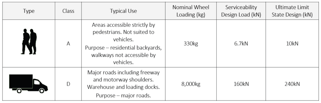
Mactrap grease traps can be installed below ground. The upper surface of the grease trap is not considered load bearing, so if the installation will carry load (pedestrian or vehicular) then risers and covers should be installed.

  • Mactrap passive traps are available with HDPE trafficable lids in Class A (pedestrian) and Class D (vehicular).
  • Flexible coupling allows easy installation into the surrounding medium.
  • Surrounding concrete or other medium must be engineered to the appropriate loading.
  • The lids are sealed and are manufactured to Class A & D specifications. The riser(s) default length is 450mm but can be supplied at any length up to 2m.
  • The riser mounts are pre-welded and the riser flanges and screw on lids are provided separately. The riser flanges and screw on lids are installed once the exact height of the installation is known. The risers can be cut on site to the required height.

Class AD Riser & Cover

Location
  1. Install the grease trap in a location that is accessible by manual or vacuum tanker so that it can be regularly cleaned out.
  2. The Class A and Class D lids are in the form of a variable height riser that the cover fits over and is settled into a load bearing pedestrian or traffic strata. These are to be inserted into concrete or surround.
  3. An engineer’s detail is required to ensure the risers and cover plates are set and located on a substrate that will hold the appropriate class cover. This means a concrete surround or steel frame to engineer’s requirement installed above the grease trap to take traffic weight.
Load Bridge
  1. Ensure that the load bridge extends at least 600mm onto the surrounding stable ground.
  2. The Class D vehicular load bridge must be constructed using reinforced concrete. An engineer’s detail is required for the load bridge specification for heavy vehicles.
Ground Water
  1. If the grease trap is installed in areas with high water tables, or in areas subject to flooding, then the installation must include restraints or engineered load bridge that prevent the grease trap from floating out of the ground.
  2. If 70% of the grease trap’s storage capacity falls below the flood level, then anchor the grease trap.
Venting
  1. The grease trap must be vented off either inlet or outlet, close to the tank, to ensure good ventilation.
  2. The grease trap can be vented from the top surface if required. If installing a vent from the top surface of the grease trap, then install a 50 -100 mm vent (depending upon local authority requirement) using a bulkhead fitting or appropriate seal.
  3. If the outlet is direct to sewer, then local authority regulations may mandate a vent on the outlet.
Backflow prevention
  1. If backflow prevention is a local authority requirement, then the
  2. backflow prevention device should be installed within five metres of the grease trap.
Connections
  1. The invert level of inlet and outlet are set. Do not raise or lower the inlet or outlet. If the invert of the outlet is too high the inlet connection may be submerged. The invert of the outlet pipe must remain lower than the invert of the inlet pipe.
  2. The outlet pipe must never be of lesser diameter than the inlet pipe.

Further Information

Grease Boss EasyClean

G15/G25

Installation Instructions

Grease Converter

ChemiClean

Installation Instructions

Support • Information • Design • Sizing

Need Help?